 |
| Parts being laid out in their respective sub assembly's at Melrose. Click here for another view. Link here: Life magazine 1942. |
 |
| Data plate from a Melrose Park Buick engine. |
 |
| A view of the almost completed factory in Melrose Illinois. This is a south facing view. |
 |
| Same as below, only different contrast. |
 |
| Nettie Rowe weighing cylinder head nuts. This is the Melrose factory, judging by the height of the light fixtures. |
 |
| Inspecting the pistons that were cast in Flint. These were matched according to weight just as automobile engines. |
 |
| Installing the piston rings. |
 |
| The master rods are being readied for assembly. |
 |
| Directly above are the regular rods. These were forged in Flint. |
 |
| The barrel before and after machining. The raw castings and the basic machining was done in Flint.The barrel serves the same purpose as a conventional engine block. |
 |
| This partial assembly shows the relationship of the barrel, head and crankcase. This is also a good look at the MASTER ROD. |
 |
| These are the almost finished barrels that the piston travels in. They still require the holes drilled that will allow them to be bolted to the crankcase. |
 |
| An assembly aid being shown on the center section of the engine crankcase. Link here for Crankcase X RAY. |
 |
| Machining a Liberator crankcase at Melrose. |
 |
Machining a Liberator crankcase at Melrose.
|
 |
| Machining a Liberator crankcase at Melrose. |
 |
| Machining a Liberator crankcase at Melrose. |


 |
| Installing the crankshaft in the center sub assembly of the engine crankcase. |
 |
| Sub assembly of the crankcase showing the cam and tappet area. |
 |
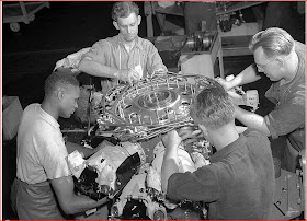
| More assembly. |
 |
| Assembly and evaluating. |
 |
| Wire loom sub assembly. This photo was obviously taken at the exact same time as the one below, judging by the reflection in the upper left corner. Another view. |
 |
| Wire loom sub assembly. |
 |
| Installing the rear bulkhead for the reduction gear of the prop shaft. |
 |
| Reduction gear sub assembly. |
 |
| More assembly. |
 |
| The tracks that these assembly stands moved along in remind me of the old craft method of assembly..see this photo. |
 |
| More assembly. |
 |
| More assembly. |
 |
| Tightening a cylinder hold down nut with one of many special tools needed for this engine. |
 |
| More assembly. |
 |
| A nice looking engine. |
 |
| Almost done. |
 |
| The finishing touch. |
 |
| The "V" for victory. This symbol was used anytime another milestone was completed. |
 |
| Final test control room. |
 |
| The final test was considered the "Acceptance" test. |
 |
| Final test. |
 |
| Final test. |
 |
| Final test. |
 |
| Final test. |
 |
| The alternators used to capture the power of these engines during their initial break-in run. "Not even this power was wasted". This resulted in an estimated savings of $80,000 dollars per month. |
 |
| Add caption |
 |
| Getting ready for the Liberator's first break-in run. |
 |
| Muscling a finished engine. |
 |
| Packing instructions. The moister detecting paper that is packed with each engine is shown in the bottom left corner. The photo with the red arrow shown farther below is this tag. |
 |
| The shipping case. These instruction manuals can be found at the link show at the end of this post. You can enlarge them there. |
 |
| Unpacking instructions are shown at the top with the vacuum seal being installed above. The red arrow above shows the water sensitive paper that would indicate the presence of moisture. |
 |
| Unpacking instructions are shown at the top with the vacuum seal being installed above. The red arrow above shows the water sensitive paper that would indicate the presence of moisture. |
 |
| This shows the pliofilm bag being sealed and evacuated of all air. |
 |
| Packaging at the Melrose facility. |
 |
| Packaging at the Melrose facility. |
 |
Packaging engines for the trip to Willow Run Michigan. The huge Ford bomber assembly plant where these engines are headed was so near to the Melrose factory that no protective vacuum packaging was required. The vacuum packaging was for engines going into storage for future use. Links: Maintenance and service manuals complete. World War II Archeology in England R-1830 "Twin Wasp" Radial Engine prop-shafts Journey Through Buick. B-24 Liberator Liberator Engine work at Buick. Buick At It's Battle Stations Link for Pratt & Whitney time-line and history. The U.S. / American Automobile Industry in World War Two / WWII An American Auto Industry Heritage Tribute By David D Jackson
|


